1 / 5
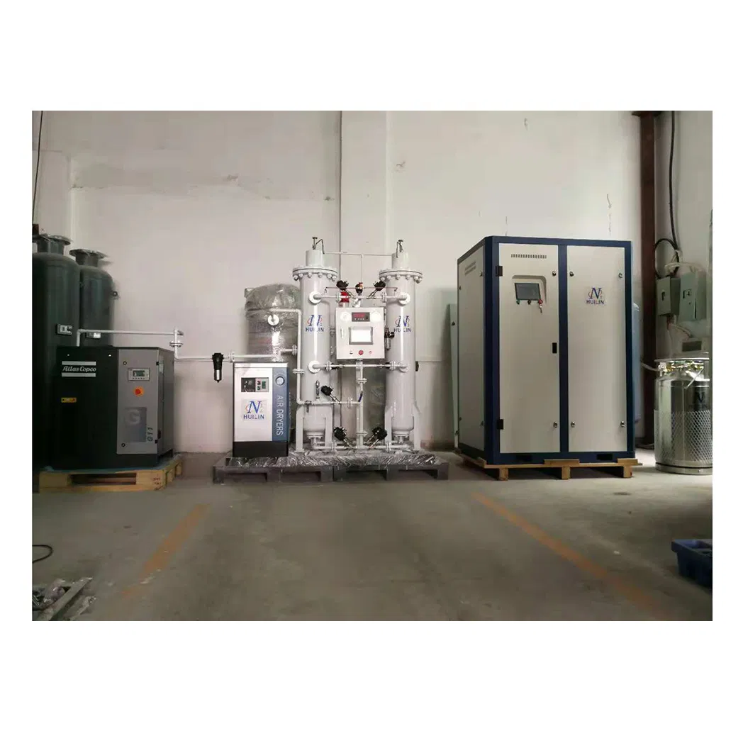
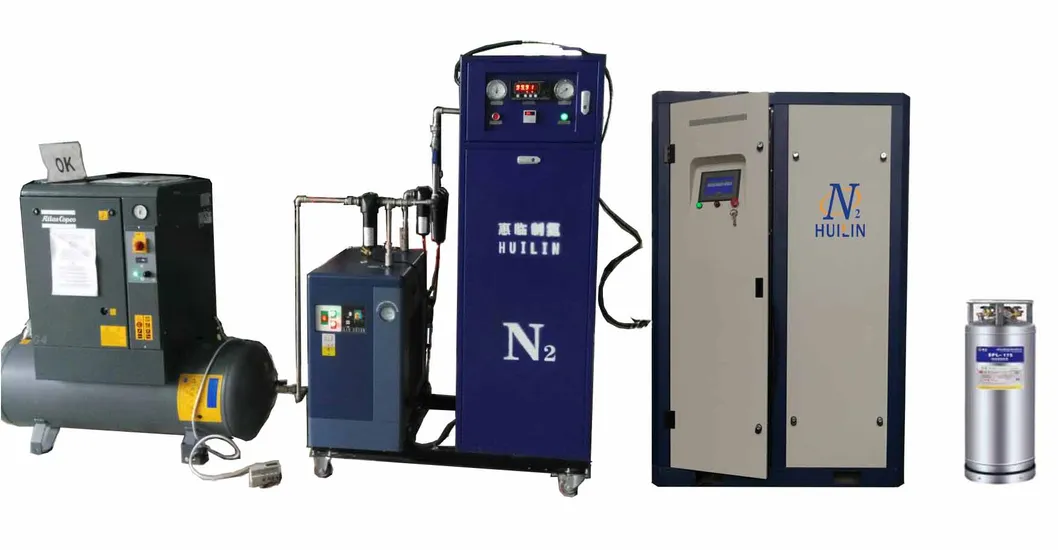
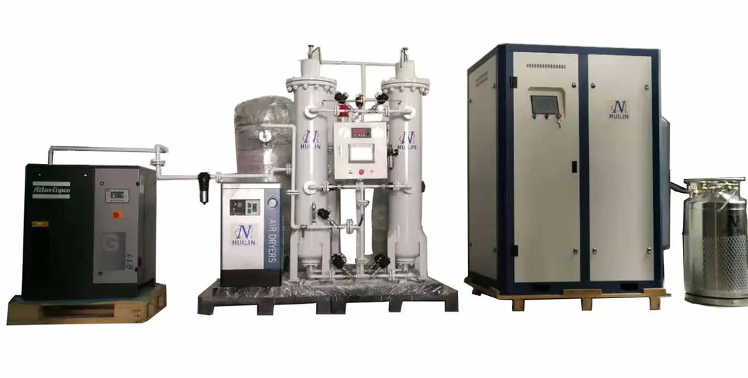
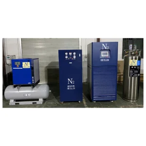
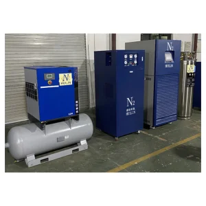
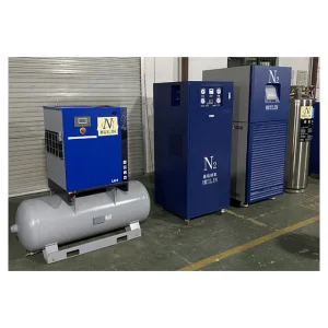
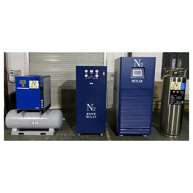
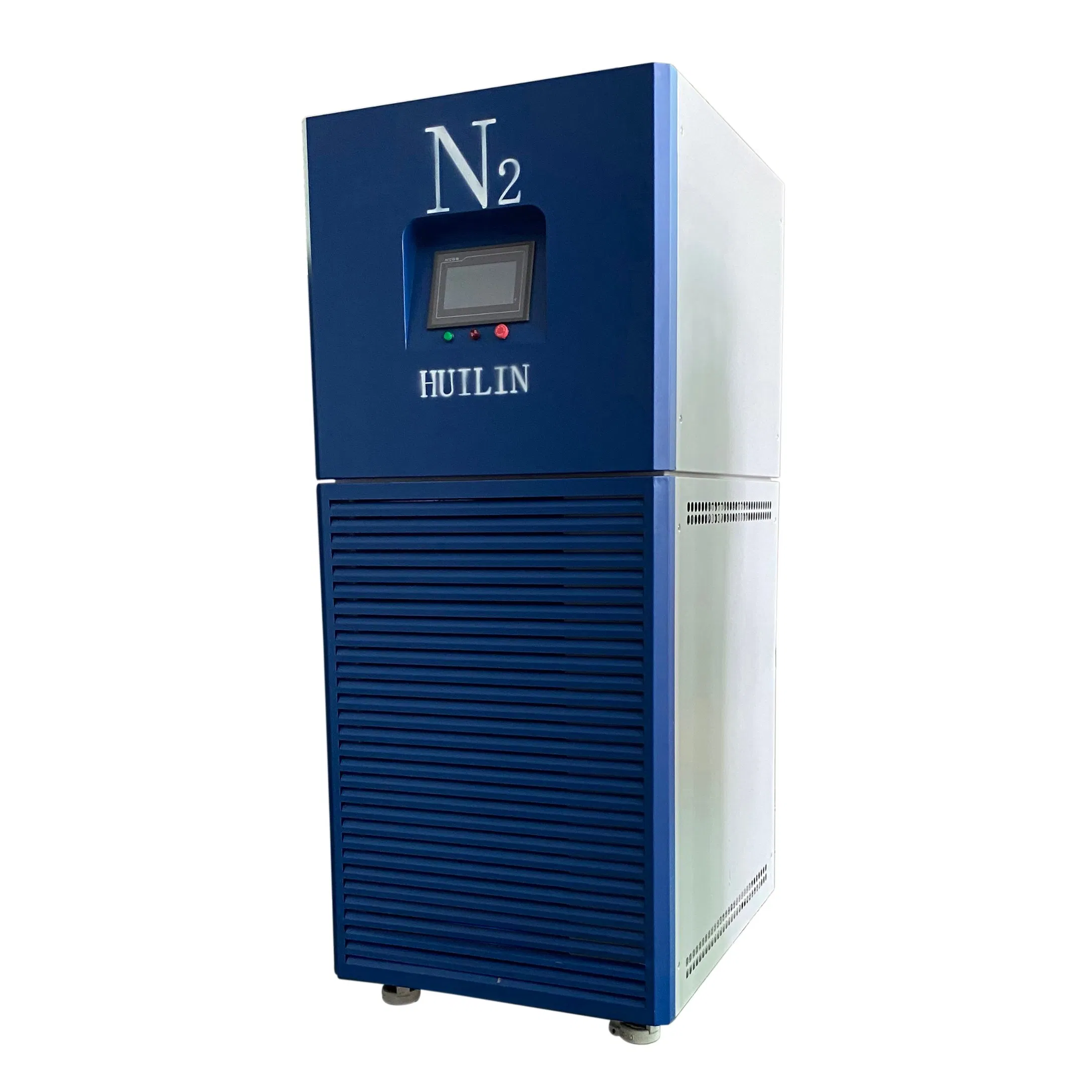
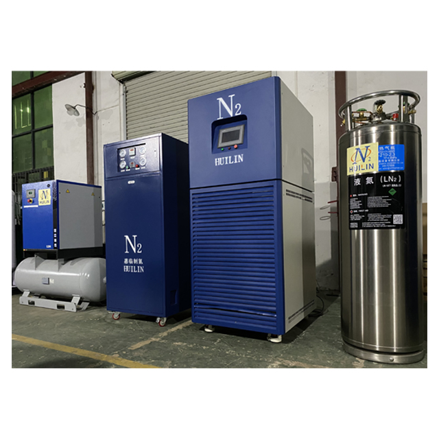
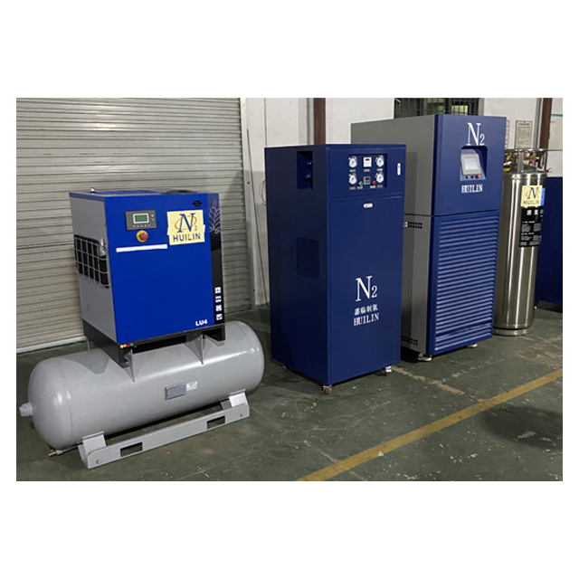
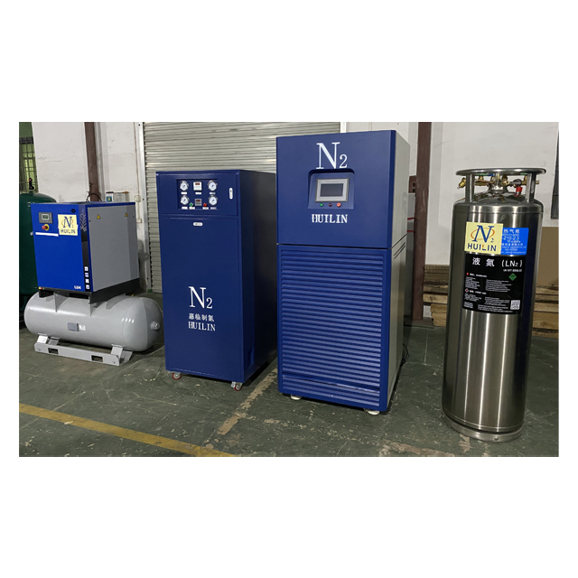
This advanced nitrogen liquefier utilizes a cutting-edge cryogenic mixed refrigerant throttle refrigerator. It employs a regenerative multi-component mixed refrigerant throttle cycle.
By artfully integrating components with varying boiling points (high, middle, and low), each component perfectly aligns with its respective refrigeration temperature zone, achieving cooling from ambient levels down to a remarkable -196 °C, culminating in the successful liquefaction of nitrogen (-180 °C @ 0.6 MPa).
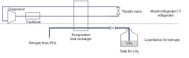
Figure 1. Flow diagram for the nitrogen liquefier
| Model | WG-STD-05L | WG-STD-1L | WG-STD-3L | WG-STD-5L | WG-STD-10L | WG-STD-20L | WG-STD-25L | WG-STD-30L | WG-STD-40L | WG-STD-50L |
|---|---|---|---|---|---|---|---|---|---|---|
| L.Nitrogen Output (L/day) | 12 | 24 | 80 | 120 | 240 | 500 | 360 | 720 | 1000 | 1200 |
| L.Nitrogen Output (L/h) | 0.5 | 1 | 3 | 5 | 10 | 20 | 25 | 30 | 40 | 50 |
| Power (KW) | 1 | 5 | 8 | 9 | 11 | 25 | 25 | 25 | 35 | 35 |
| N2 consumption (Nm³/h) | ≥1 | ≥1.5 | ≥4 | ≥6 | ≥12 | ≥30 | ≥35 | ≥40 | ≥50 | ≥60 |
| N2 Purity | 99.9% | 99.9% | 99.9% | 99.9% | 99.9% | 99.9% | 99.9% | 99.9% | 99.9% | 99.9% |
| Cooling form | Air | Air | Air | Air | Water | Water | Water | Water | Water | Water |
| Dimensions (mm) | 850×950×1960 | 1500×1000×2000 | 2500×1500×2000 | |||||||